Parametric STOP & Lightweight Optics component Optimizer
STOP Analysis (Structural, Thermal, and Optical Performance) is the industry-standard multiphysics discipline coupling structural mount deflection, thermal soak dishing, and physical wavefront error. Compress weeks of manual CAD/FEA meshing and coordinate transforms into a 1-minute cloud solve. Accurately simulate Mindlin thick plate deformations, evaluate multi-axial gravity & thermal soak, and export ISO 24157 / ISO 14999-2 Zernike files directly to Ansys Zemax OpticStudio and CODE V.

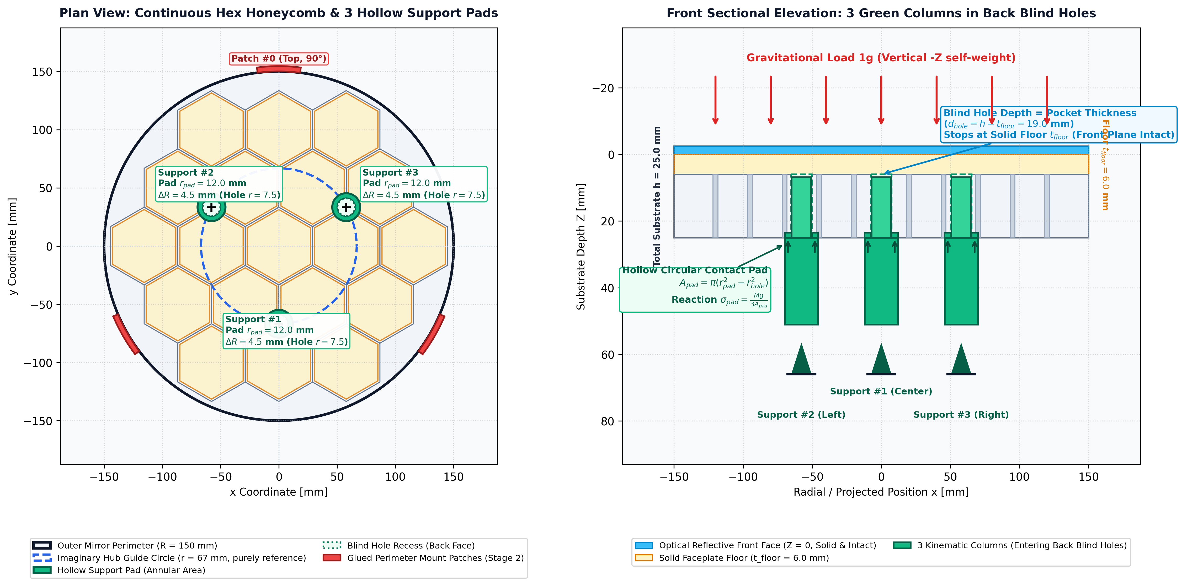 Stage 1: 3-Column Node Pads
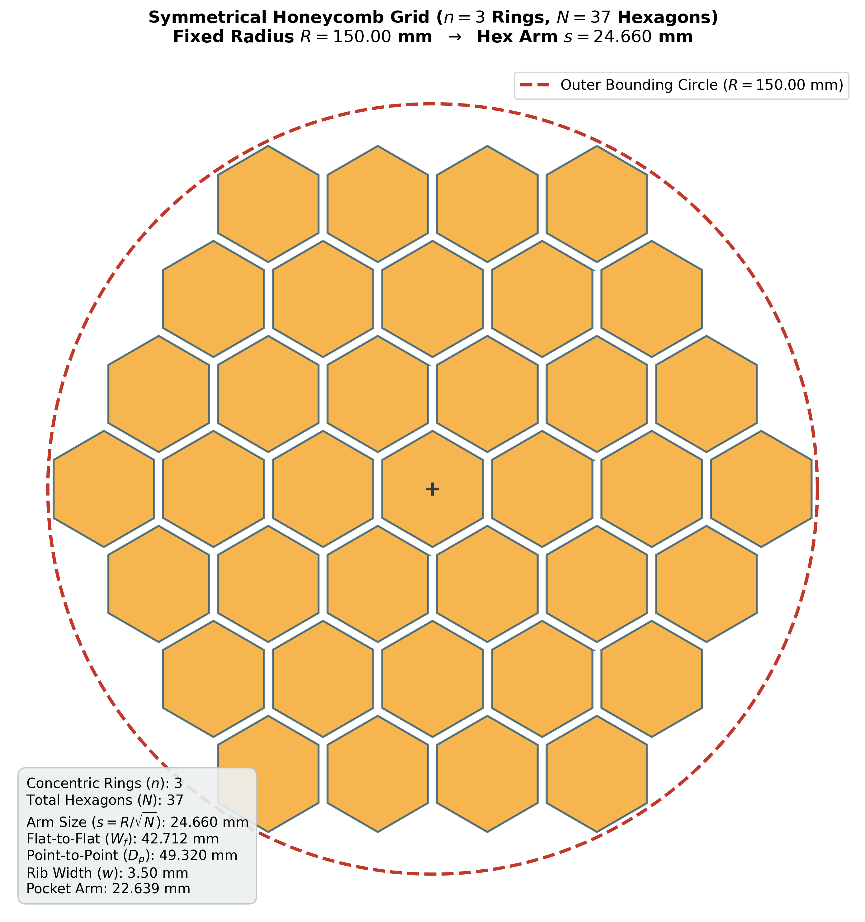 Stage 2: Honeycomb Core & Flight Mount
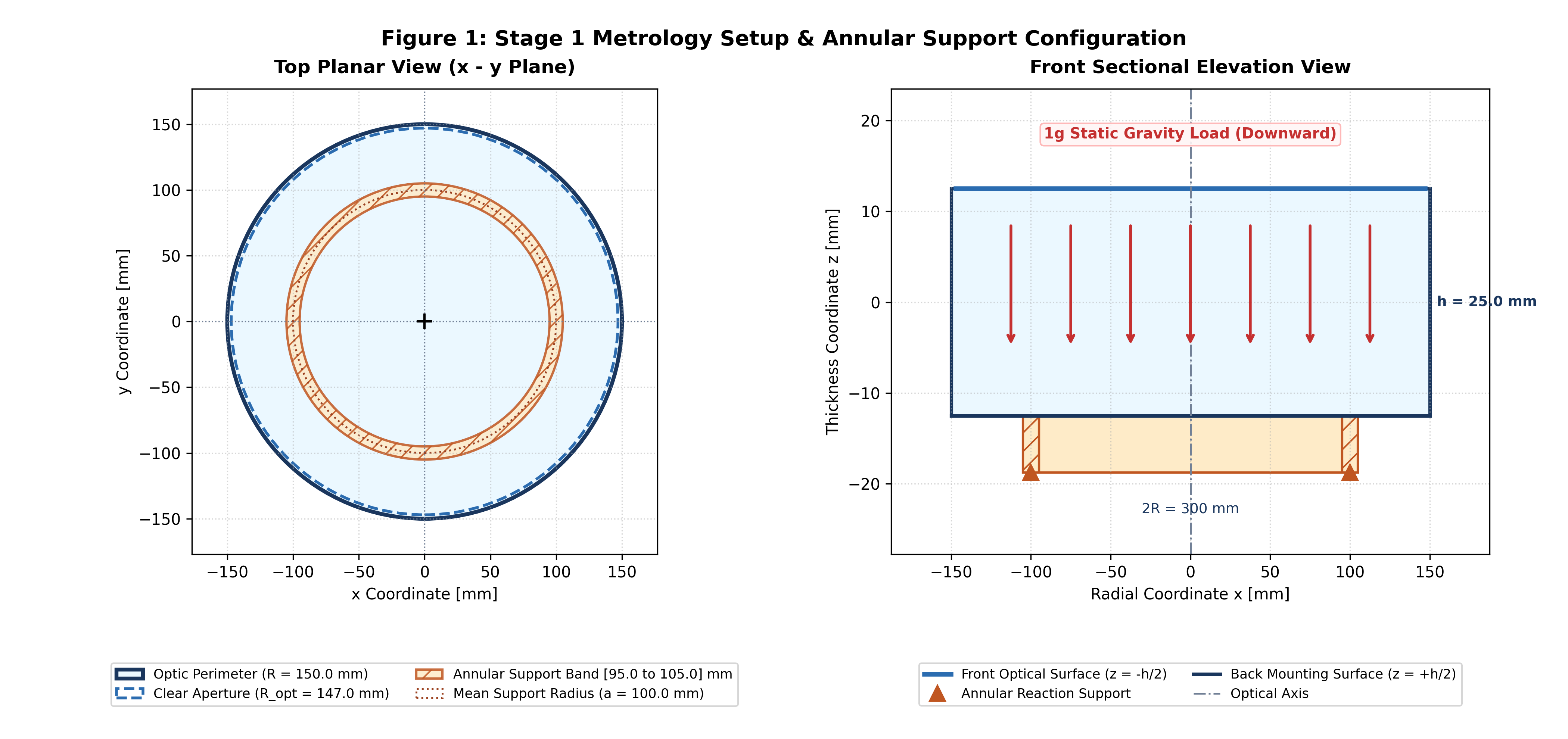 Stage 1: Annular Leveling Ring
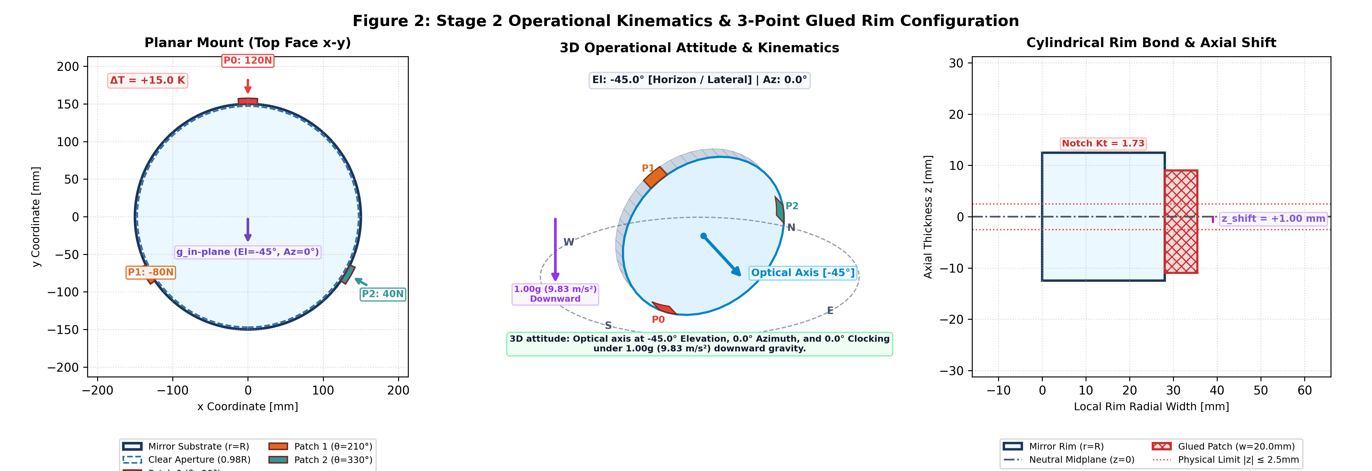 Stage 2: 3-Point Glued Rim
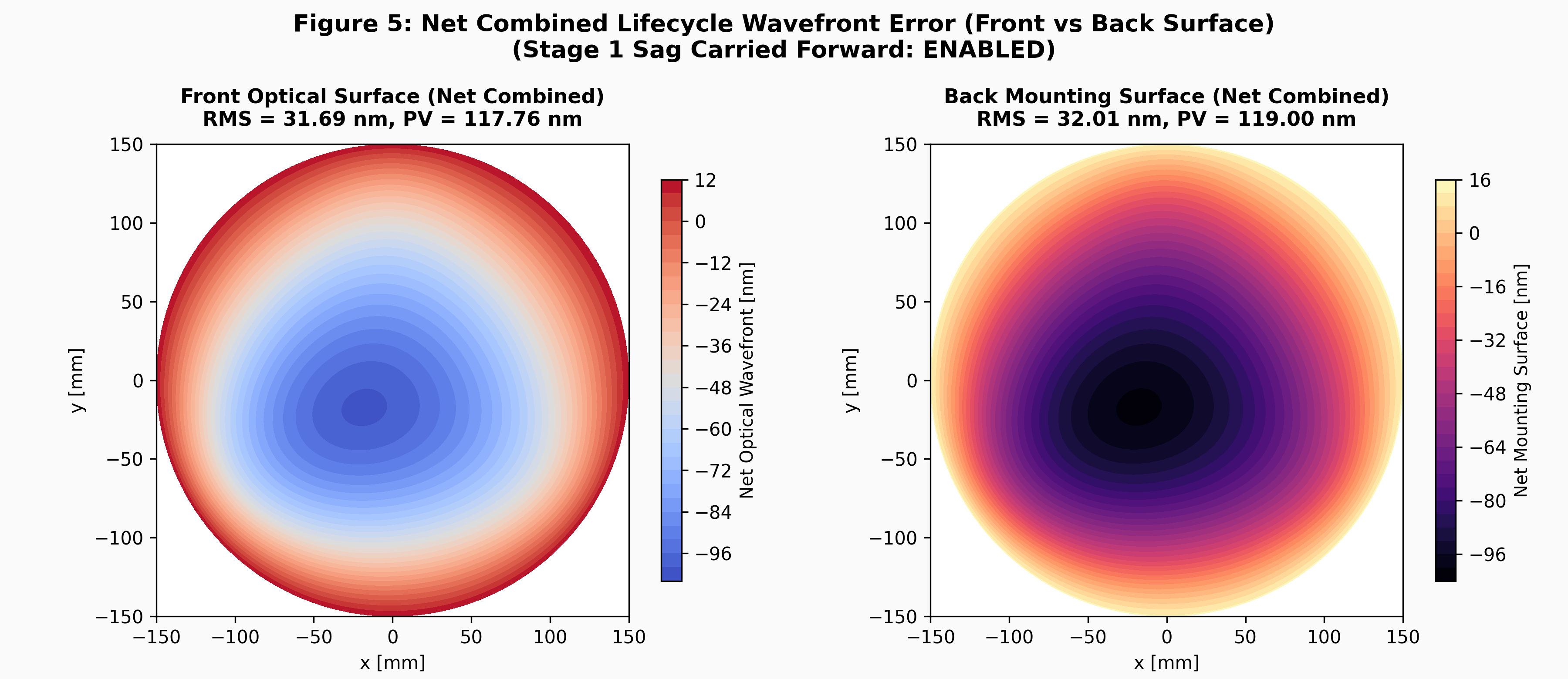 Net Operational Figure Error Contours (RMS 18.4 nm)
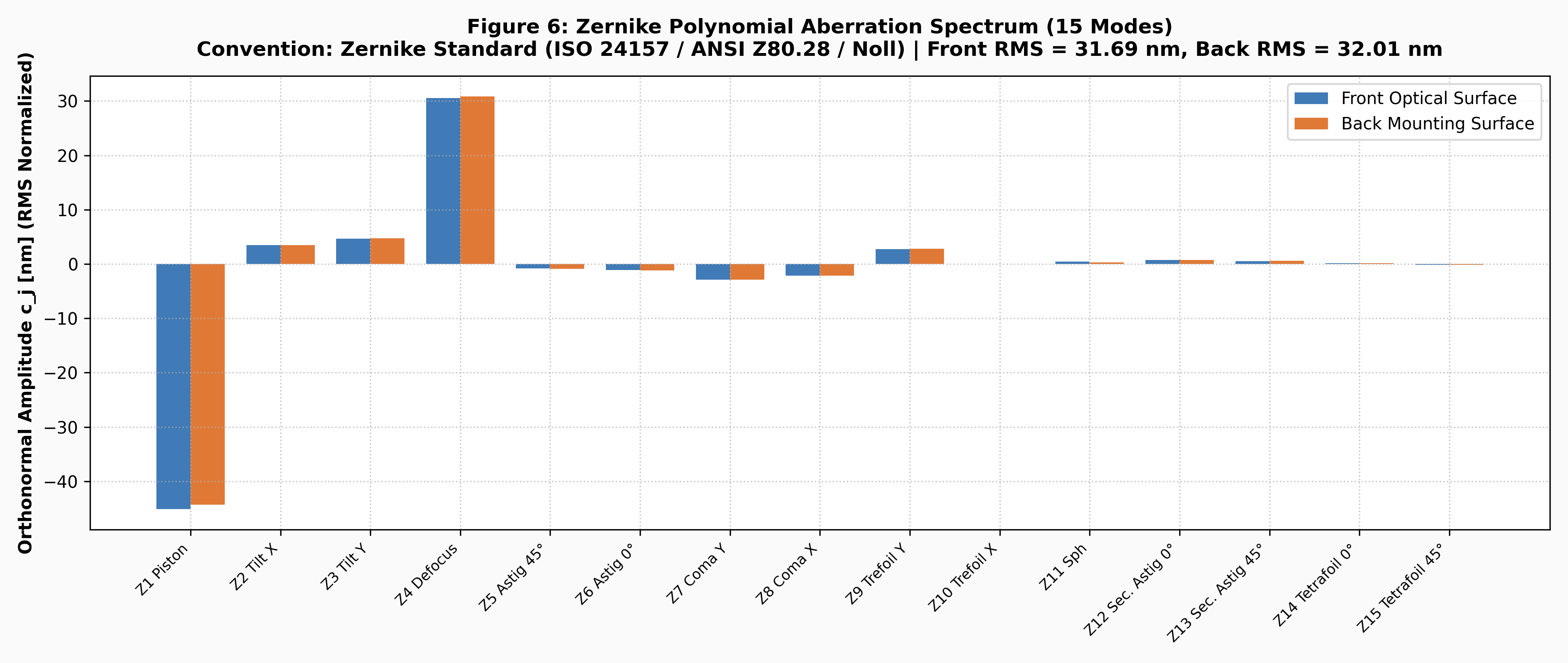 ISO 24157 Standard & Fringe Modal Coefficients
Why Traditional STOP Modeling Fails & How We Solve It
Manual FEA meshing, thin-plate assumptions, and fragmented interpolation scripts waste engineering weeks and introduce critical optical alignment errors.
What is STOP Analysis? (Structural, Thermal, and Optical Performance)
In aerospace optomechanics, astronomical telescope development, and high-energy laser design, STOP stands for Structural, Thermal, and Optical Performance. It describes the coupled multiphysics engineering analysis where mechanical mounting stresses and launch accelerations (Structural) and bulk orbital temperature variations (Thermal) are simultaneously computed to predict physical mirror sag deformations, focus shift, and wavefront aberrations (Optical Performance). Our cloud engine automates this entire pipeline, fitting orthonormal ISO Zernike polynomials and exporting ready-to-load Ansys Zemax .ZRN Grid Sag files in ~1 minute.
Traditional Multi-Tool STOP Workflow
- • Tedious 3D Brick Meshing: Days spent generating volume meshes, non-linear adhesive bonded contact pairs, and multi-point constraints in ANSYS or NASTRAN.
- • Kirchhoff Thin-Plate Underestimation: Software formulas neglect transverse shear flexibility, underestimating mirror surface deflection by 15% to 30% in thick substrates (diameter-to-thickness ratio D/h ≤ 10).
- • Fragmented Zernike Fitting Scripts: Exporting raw displacement point clouds into standalone Python/MATLAB scripts frequently introduces coordinate scaling errors and sign inversion.
- • Lack of Real-Time Optimization: Evaluating mirror mass reduction, thermal soak boundaries, and gravity tilt envelopes requires weeks of manual re-runs.
The IES Parametric STOP Cloud Engine
- • Mindlin-Reissner FSDT Formulation: Accurately accounts for transverse shear flexibility (κ2 = 5/6), matching 3D continuum brick FEA to sub-nanometer tolerance.
- • Dual-Surface Figure Mapping: Simultaneously tracks both the optical front face and the mechanical rear mounting plane to budget sag, wedge, and decenter.
- • Native Dual ISO Zernike Standards: Instant concurrent decomposition in ISO 24157 (Noll Standard, 66 modes) and ISO 14999-2 (Arizona Fringe, 37/48 modes) with zero sign ambiguity.
-
•
~1 Minute Cloud Convergence: Automated analytical and FEM cross-checked solvers generate full 300 DPI vector PDFs and Ansys Zemax
.ZRNfiles in ~1 minute.
18 Specialized Capabilities in Optomechanical Engineering and Multi-Physics, Multi-Objective, and Multi-Constraint Optimization
Engineered to model real-world telescope mirror mounts, thermal soak dishing, and multi-axial gravity tumbling with rigorous mathematical precision.
Mindlin FSDT Thick Plate Mechanics
Formulates First-Order Shear Deformation Theory (FSDT) with shear correction factor κ2 = 5/6, accurately capturing flexural and transverse shear strains in thick substrates (diameter-to-thickness ratio D/h ≤ 10).
Two-Stage Lifecycle Kinematics
Simultaneously evaluates Stage 1 manufacturing metrology on a continuous leveling ring and Stage 2 operational retention on 3 glued rim pads at 120° with automated carry-forward differential subtraction.
Annular Metrology Ring Optimization
Sweeps support radius amfg across the Airy / Bessel minimum-sag envelope (~68% to 70% of outer radius R) with finite support band width ΔR to minimize metrology print-through.
3-Point Glued Outer Rim Retention
Models standard flight kinematic mounting: 3 discrete bonded elastomeric rim pads at 120° intervals with defined axial patch height w and circumferential arc length l.
3D Tri-Axial Gravity Tilt Kinematics
Resolves the gravity vector into axial (gz = −g × sin(θel)) and lateral (glat = g × cos(θel)) components across Elevation θel (±90°), Azimuth β (0–360°), and In-Plane Clocking.
Custom Gravitational Acceleration g
Fixed condition parameter defaulting to nominal 1.0g = 9.8314 m/s2 with bounds defaulting to 1.0g. Fully supports orbit microgravity (0.0g) and launch vibration survival (up to 20g).
Adhesive Offset & Line Moment Mpad
Calculates bending line moments Mpad = Fr × zshift / lpatch caused by axial offset between the adhesive bond center and the neutral bending surface, predicting mount-induced astigmatism.
Uniform Bulk Thermal Soak ΔT
Models space soak temperature shifts (ΔT), coupling CTE expansion against adhesive line moments to accurately predict spherical power drift (focus shift) and thermal dishing.
ISO 24157 Noll Standard Zernike
Decomposes optical wavefront surface error into orthonormal Zernike polynomials (up to 66 modes) with continuous radial normalization over the active optical clear aperture.
ISO 14999-2 Arizona Fringe Zernike
Computes University of Arizona Fringe Zernike decompositions (37 or 48 terms), enabling seamless 1:1 integration with Ansys Zemax OpticStudio, CODE V, and Zygo interferometers.
Dual-Surface Figure Mapping
Independently extracts and maps deformation profiles on both the front optical clear aperture and the rear structural mounting plane, budgeting axial thickness variation and wedge.
Optical Figures of Merit Budgeting
Calculates exact optical figures of merit including RMS Wavefront Error, Peak-to-Valley (PV), Primary Astigmatism (Z5, Z6), Power/Focus (Z4), Trefoil (Z9, Z10), and surface slope.
Space-Grade Substrate Library
Pre-configured thermodynamic and mechanical property library for ultra-low expansion glass (Zerodur, ULE), Fused Silica, Silicon Carbide (SiC), Beryllium, and Invar-36.
Von Mises Stress & Notch Safety
Performs stress concentration analysis around pad notches and support perimeters, ensuring the structural design satisfies strict brittle fracture safety factors (Safety Factor SF ≥ 1.50).
Ansys Zemax & CODE V Direct Export
Generates ready-to-load .ZRN Grid Sag files and interferogram tables formatted for immediate importation into Ansys Zemax OpticStudio and Synopsys CODE V optical design software.
Python FEM & FreeCAD Benchmark
Features an integrated Python continuum plate FEM validator benchmarked against CalculiX (ccx) and FreeCAD S8R/S4R quadratic elements, ensuring analytical convergence within 2%.
300 DPI Vector PDF Deliverables
Automatically compiles high-resolution vector contour maps, modal spectrum bar charts, deflection line profiles, and certification tables into publication-grade ReportLab PDFs.
Institutional Purchase Orders & SAC 998145
Designed for formal procurement by government space agencies, astronomical observatories, and universities with GST Rule 46 compliance under SAC 998145 (Scientific Consulting).
Supported Domains & Multiphysics Environments
Comparative overview of dominant structural loads, thermal drivers, and critical optical wavefront criteria solved by the STOP engine across 11 precision optical sectors.
| Optical Segment & Mission Class | Dominant Structural Driver | Primary Thermal Driver | Critical Optical Impact |
|---|---|---|---|
| 🚀 1. Spacecraft & CubeSat Payloads | Launch acoustic/vibration loads & 0g gravity release | Extreme orbital solar/albedo cycles & deep-space radiative sinks | Sub-micron focal plane shift, line-of-sight (LOS) pointing drift, wavefront errors (WFE) |
| 🔭 2. Ground Astronomical Observatories | Slewing gravity vector changes & turbulent wind buffeting | Diurnal ambient air swings & localized dome heat plumes | Segmented mirror piston/tip/tilt misalignment, seeing degradation, phase errors |
| 🩺 3. Medical & Surgical Laser Scanners | High-speed dual-axis galvo inertia & handpiece micro-motions | Localized optical absorption from high-power pulsed/CW beams | Thermal lens blooming, focal spot defocus at tissue plane, scan beam wander |
| 🔬 4. Semiconductor Metrology Optics | Multi-axis reticle/wafer stage accelerations & step vibrations | Sub-wavelength laser flux absorption (DUV/EUV plasma radiation) | Sub-nanometer surface distortion, optical compaction, critical dimension (CD) overlay error |
| 💥 5. Directed Energy Weapons (DEW) | Dynamic gimbal steering torque & optical mount micro-creep | Multi-kilowatt bulk transmission absorption & mirror heating | Severe thermal lensing, destructive thermal blooming, phase profile collapse |
| 🛩️ 6. Airborne & Defense ISR | Dynamic boundary-layer pressure & airframe vibration | Harsh operational swings (−55°C to +70°C) & aerodynamic skin friction | Conformal window defocus, image smear, line-of-sight (LOS) jitter |
| ⚛️ 7. Scientific Synchrotrons & FEL Beamlines | Sub-micron mechanical mounting strain & vacuum chamber stresses | Extreme localized micro-spot X-ray thermal flux density | Crystal d-spacing lattice distortion, grazing mirror micro-radian slope errors |
| 🚗 8. Automotive ADAS & Autonomous Optics | Chassis shocks, continuous road vibrations, and engine resonances | Direct cabin/windshield solar baking & sub-zero cold starts | Athermal focal shift, lens adhesive degassing, machine-vision false positives |
| 📡 9. Terrestrial FSO & QKD Networks | High-rise building sway & base tower wind deflection | Outdoor ambient solar flux cycles & thermal gradients | Beam footprint wander, spatial light coupling loss, quantum phase mismatch |
| ⚙️ 10. Industrial Laser Material Processing | Rapid CNC/gantry translation dynamics & high-G scan reversals | Multi-kilowatt fiber laser absorption & workpiece back-reflections | Focal position drift (z-shift), spot elongation, inconsistent cut/weld kerf width |
| 🌊 11. Oceanographic & Deep-Sea Optics | Extreme hydrostatic compressive stress (100 to 1,000+ bar) | Abyssal cold water heat sinks (1°C to 4°C) vs. thermal plumes | Pressure-induced window curvature bending, optical aberration, depth defocus |
Dynamic Slabs Based on Optimization Search Scale
Fair, predictable pricing structured for single research studies or comprehensive multi-variable mission sweeps. Start free with Tier 0 (Free Demo), or scale up with instant Razorpay, UPI QR, or PayPal checkout.
Baseline Verification
1 Verification Point • Nominal Config
- ✓ Stage 1 & Stage 2 Quick Solve
- ✓ Full Dual Zernike Decomposition
- ✓ 300 DPI Vector PDF Report
- ✓ Demo Certificate & Tax Invoice
Optomechanical Study
50 Grid Search Design Points
- ✓ 50-point parametric trade sweep
- ✓ Thickness vs. Sag trade study
- ✓ Ansys Zemax .ZRN Grid Sag file
- ✓ Complete Deliverable ZIP Package
Observatory R&D
250 Grid Search Points
- ✓ Dual-stage multi-objective solver
- ✓ Python FEM benchmark cross-check
- ✓ Thermal soak ±50K envelope sweep
- ✓ Zernike Fringe 37/48 + Standard 66
Flight Space Mission
1,000 Grid Search Points
- ✓ 1,000-point mission sensitivity
- ✓ 3D gravity tilt sphere (Zenith/Nadir)
- ✓ High-res vector CAD schematics
- ✓ Formal Institutional PO & SAC Invoice
Annual Pass
5,000+ Points • Max 5 Runs/Month
- ✓ Maximum 5 optimization runs per calendar month metered by internal system clock (resets 1st of each month at 00:00:00 UTC)
- ✓ Multi-project annual allocation (up to 60 deep search evaluations annually)
- ✓ Internal system clock quota tracking & automated monthly cycle rollover
- ✓ 5,000+ Deep Grid Search points & active infill optimization per run
- ✓ Priority cloud compute daemon & dedicated Engineering Concierge Review
Razorpay Gateway
Instant automated order authorization! Accepts Corporate & Personal Cards (Visa, Mastercard, Amex), Corporate Netbanking, and UPI.
Domestic UPI Payment
Direct Indian banking transfer via GPay, PhonePe, Paytm, BHIM, or institutional bank UPI. Enter your 12-digit UTR receipt number for instant verification.
PayPal.Me Checkout
For international observatories and aerospace research teams: Pay securely via connected PayPal balance or overseas institutional accounts.
Inspect Real STOP Engineering Deliverables
Preview our publication-quality 300 DPI vector PDFs, Ansys Zemax .ZRN Grid Sag files, and high-resolution CAD schematics generated by the ThickPlateSTOP Cloud Engine.
Scientific STOP Summary Report
Complete engineering report featuring Stage 1 & Stage 2 figure contour plots, modal decomposition tables, stress concentrations, and optical margin budgets.
Full Engineering Deliverable ZIP
Comprehensive packages bundling summary PDF, Ansys Zemax .ZRN Sag files, Zernike CSVs, PNG plots, JSON outputs, and STEP CAD.
Stage 1 Metrology Schematics
High-resolution metrology blueprints detailing mirror clear aperture, center sag, mean radius amfg (Option A annular ring) and 3-column node pads (Option B honeycomb).
Stage 2 Flight Mount Schematics
Operational mounting diagrams showing 3 outer rim bonded pads at 120° (Option A) and lightweighted honeycomb pocket backing with kinematic retention (Option B).
How Automated STOP Optimization Works
Obtain structural, thermal, and optical performance results with zero manual meshing.
Define Geometry & Envelopes
Specify mirror radius R, thickness h, adhesive pad height w, shift zshift, thermal soak ΔT, and 3D gravity tilt angles (θel, β). Or upload a pre-configured JSON configuration.
Automated Cloud Convergence
The analytical FSDT engine and Python FEM validator concurrently solve flexural and shear deformations, subtract Stage 1 metrology baseline, and fit ISO Zernike modal polynomials in ~1 minute.
Download Ready Deliverables
Track progress in My Orders and instantly download your completed 300 DPI vector PDF report, Ansys Zemax compatible .ZRN Grid Sag file, CSV coefficient tables, and formal GST Tax Invoice.
Frequently Asked Questions & Technical Clarifications
Detailed answers explaining the underlying optomechanical formulations, conventions, and procurement pathways.
What does the abbreviation "STOP" stand for in optomechanical engineering?
STOP is an acronym for Structural, Thermal, and Optical Performance. In telescope systems, space satellite payloads, and high-energy laser optics, mirrors are subjected to mechanical retention forces and gravity (Structural) as well as operational temperature shifts (Thermal). STOP analysis is the multiphysics modeling discipline that evaluates how these combined physical stresses warp the mirror substrate and degrade wavefront clarity, focal stability, and resolution (Optical Performance). Our cloud optimizer executes this entire coupled pipeline in ~1 minute, delivering ISO Zernike coefficients and Ansys Zemax .ZRN files.
Why does First-Order Shear Deformation Theory (FSDT) outperform Kirchhoff thin-plate theory for telescope mirrors?
Precision telescope primary and folding flat mirrors generally feature thickness-to-diameter aspect ratios between 1:6 and 1:10 (thick plate regime). Classical Kirchhoff plate theory assumes surface normals remain straight and strictly perpendicular to the deformed mid-surface, completely neglecting transverse shear strains (γrz). In thick substrates, transverse shear contributes between 15% and 30% of the total optical sag. FSDT (Mindlin-Reissner theory) incorporates transverse shear flexibility with a shear correction factor (κ2 = 5/6), delivering sub-nanometer correlation with 3D solid continuum brick FEA.
How does adhesive axial shift (zshift) create edge line moments and optical wavefront astigmatism?
When the outer rim adhesive bonding pad center is offset from the mirror neutral bending plane by an axial distance zshift, the radial mounting retention force Fr exerts an active bending line moment Mpad = Fr × zshift / lpatch. Because the mount consists of 3 discrete pads at 120-degree intervals, this localized line moment induces significant trefoil (Z9, Z10) and astigmatism (Z5, Z6) across the optical clear aperture.
What is the difference between ISO 24157 (Noll Standard) and ISO 14999-2 (Arizona Fringe) Zernike polynomials?
ISO 24157 (Noll / ANSI Standard) indexes Zernike modes sequentially using radial degree n and azimuthal frequency m, maintaining strict orthonormal properties over the unit pupil up to 66 modes. ISO 14999-2 (University of Arizona Fringe convention) orders modes by optical significance (up to 37 or 48 terms) and is the native format for Ansys Zemax OpticStudio, CODE V, and Zygo interferometers. Our platform computes both standards concurrently with zero rounding error.
How are Stage 1 (assembly sag) and Stage 2 (operational flight) kinematics combined?
During mirror assembly, the fabricated optic is positioned on temporary Stage 1 metrology supports under 1g gravity self-weight sag: on a continuous annular leveling ring (mean radius amfg, width ΔR) for Option A Solid Optics, or on 3 kinematic circular column pads at 120° rib-joint nodes for Option B Honeycomb Optics. While in this resting state, three mechanical mounting blades are bonded to the cylindrical outer perimeter patches with structural adhesive. Once the adhesive slowly cures and fully solidifies at the three patches with those areas fixed, the temporary Stage 1 support is released and removed. Because the assembly sag is locked into the optic at bond solidification, the full Stage 1 deformation remains permanently locked into the substrate. When subsequent operational loads—such as 3D gravity pointing tilt, thermal soak ΔT, and mount forces—are applied in Stage 2, the operational flexure superimposes onto this locked-in sag. When Stage 1 Carry-Forward is enabled, the net operational wavefront error is the cumulative sum of both states: wnet = wmfg + wop (manufacturing sag + operational flexure).
How do the Elevation (θel), Azimuth (β), and In-Plane Clocking angles orient the gravity vector?
The gravity acceleration vector is decomposed into axial and lateral components: gz = −g × sin(θel) and glateral = g × cos(θel). Azimuth β rotates the lateral vector in the mirror coordinate plane relative to Mount Pad 0, while In-Plane Clocking rotates the entire mirror assembly about its optical vertex, allowing complete simulation of tumbling orbiters or alt-azimuth gimbal tracking.
Can we simulate zero-gravity (0g) orbit operations or high-G launch survival?
Yes. Gravity load magnitude g is a dedicated fixed parameter (default 1.0g = 9.8314 m/s2). Setting g = 0.0g simulates microgravity space orbit, where only thermal soak ΔT and adhesive shrinkage actuate mirror figure change. Conversely, inputting 2.0g to 15.0g simulates launch ascent acceleration and quasi-static acoustic loads, verifying safety factors against brittle fracture.
What deliverables and optical software file formats does the STOP optimizer produce?
Every completed order provides:
- 📄 300 DPI Vector PDF Report: Comprehensive engineering documentation with 3D contour plots, Zernike bar spectrums, and safety factor margins.
- 📁 Ansys Zemax OpticStudio
.ZRNFiles: Standard grid sag surface map ready for instant ray-tracing and MTF degradation analysis. - 📊 CSV & JSON Matrices: Full numerical tables of Zernike coefficients, surface sag points, and stress profiles.
- 📦 Deliverable ZIP Package: All simulation files, vector plots, and CAD schematics bundled into a single archive.
How does the Python FEM validator cross-check the analytical Mindlin plate solution?
The platform incorporates a built-in Python continuum finite element solver with First-Order Shear Deformation kinematics and selective reduced integration (S8R/S4R element equivalent). When FEM validation is checked, the backend automatically discretizes the mirror domain, applies boundary kinematic constraints, and correlates central deflection and peak Von Mises stresses, guaranteeing analytical agreement within 2% against CalculiX and FreeCAD benchmarks.
How can government research institutions and universities procure via formal Purchase Order (PO) and SAC 998145?
Researchers and procurement managers can select Institutional Purchase Order billing at checkout, enter their organization's PO reference number, and upload PO documents. The system issues a formal GST Rule 46 Tax Invoice classified under SAC 998145 (Scientific & Technical Consulting Services), supporting both Indian NEFT/RTGS direct institutional billing and international wire transfers.
Can we evaluate the STOP optimizer for free before purchasing an enterprise tier?
Yes, Tier 0 (Starter Sensitivity) is 100% free with zero credits required. It computes nominal Stage 1 manufacturing and Stage 2 operational retention solutions, performs complete dual Zernike decomposition, and generates a downloadable vector PDF report and demo invoice.
How is the Tier 4 (Institutional Annual Pass) monthly quota structured and tracked?
The Tier 4: Institutional Annual Pass (₹50,000 / $599) includes up to 60 deep search optimization evaluations over a 12-month license, structured for laboratory multi-project workloads. To ensure balanced server resource allocation and guarantee priority daemon queueing, Tier 4 is configured with a maximum limit of 5 optimization runs per calendar month. Quota consumption is metered in real time against the server's internal system clock (synchronized to UTC), resetting automatically on the 1st day of each calendar month at 00:00:00 UTC.
How many constraints are addressed in STOP optimizations?
The STOP Optimization Engine resolves multi-physics structural-thermal-optical trade-offs by enforcing a comprehensive matrix of 25 constraint parameters for Option A (Solid Optics) and 28 constraint parameters for Option B (Lightweight Honeycomb Mirror).
| Architecture | Total Constraint Parameters Addressed | Core Physical/Optical Constraints | Geometric & Topology Bounds | Operating Envelopes |
|---|---|---|---|---|
| Option A (Solid Optics) | 25 Parameters | 12 Constraints | 7 Bounds | 6 Envelopes |
| Option B (Honeycomb Mirror) | 28 Parameters | 12 Constraints | 10 Bounds | 6 Envelopes |
- • Surface RMS: σw ≤ RMSallow (Diffraction limit)
- • Peak-to-Valley: PV ≤ PVallow (≤ 200 nm)
- • Zernike Power: Z4 ≤ 50 nm (Focus budget)
- • Astigmatism: √(Z52 + Z62) ≤ 20 nm
- • Trefoil Print-Through: √(Z92 + Z102) ≤ 20 nm
- • Stage 1 Sag / Stage 2 Flex: w ≤ 10 μm
- • Von Mises Stress: FS ≥ 3.0 (σvm ≤ σy / 3.0)
- • Brittle Tensile: FS ≥ 2.0 (σ1 ≤ σt / 2.0)
- • Contact Patch Pressure: qpad ≤ 500 kPa
- • NASA-STD-5001B Shear: τglue ≤ 3.33 MPa (25g axial)
- • NASA SP-8007 Rigidity: Aspect ratio 2R/h ≤ 15.0
- • Shared Geometry (7 Bounds): Mirror outer radius R, substrate thickness h (10–80 mm), center hole r0, mount triad radius rtriad (0.2R–0.9R), pad radius rpad (5–40 mm), Stage 1 ring radius amfg, and ring contact width ΔRmfg.
- • Honeycomb Core Additions (3 Bounds):
- - Front Floor Sheet: tfloor ≥ 3.0 mm (prevents polishing pocket quilting).
- - Isogrid Rib Wall: wrib ≥ 1.5 mm (CNC milling DFM tooling limit).
- - Hex Pocket Rings: Nrings ∈ [1, 4] (controls pocket span & core depth hcore = h − tfloor).
- • Thermal Soak: ΔT ∈ [−50°C, +50°C] CTE expansion mismatch.
- • Elevation Angle: θelev ∈ [0°, 90°] (horizon to zenith pointing).
- • Azimuth Tracking: β ∈ [0°, 360°] lateral gravity vector alignment.
- • Assembly Clocking: φclock ∈ [0°, 360°] in-plane mount orientation.
- • Mount Clamping: Radial retaining pre-load Fr ∈ [0, 500 N].
- • Stage 1 Carry-Forward: 1g self-weight sag permanently frozen at bond cure.
Ready to Optimize Your Flight Telescope Mirror?
Launch the interactive cloud configurator, select your optical substrate, define thermal and gravity boundaries, and generate publication-grade STOP (Structural, Thermal, and Optical Performance) deliverables in ~1 minute.